by John Walt Childers, IPC-CID, Founder of Golden Gate Graphics

Formerly known as

GLOSSARY of Printed Circuit Design and Manufacturing

This glossary has key terminology in use in PCB design and manufacturing, with a smattering of electronics. The definitions were chosen so that their context would likely apply to reading material encountered by a PCB designer. Therefore, many of these terms will have other meanings not given here. It is recommended by scholars that you also clear up the non-technical definitions in regular dictionaries. There are such dictionaries recommended below.

This collection of terms came about as I, a PCB designer, ran across words and acronyms in my field for which meanings were hard to find. As I tracked them down, I made them part of this glossary. If you are a PCB designer, then this glossary could be a good place to start when you find a need to look up the meanings of words related to printed circuits or electronics.

Al­pha­bet­iz­ing Me­thod

Terms that begin with a symbol or a digit are placed in the SYMBOLS page. Terms that contain digits within them are alphabetized as if the numeric characters were spelled in English.

Terms with two or more words are alphabetized "dictionary style." They are alphabetized as though the spaces between the terms have been removed.
   If there are other characters in the term, such as a slash (/), dash (-) or plus sign (+), these are treated the same as spaces and ignored for the purpose of alphabetizing.

Click for Pronunciation Key


References and Dic­tio­nar­ies

Modern Dic­tio­nary of Elec­tron­ics by Rudolf F. Graf

This is the best, most usable dictionary for electronics, because its definitions help you grasp the terms and therefore the subject. Lesser dictionaries define electronics terms with even more difficult technical jargon, leading one into endless"word chains." Not this one.
You can buy the Modern Dictionary of Electronics new or used via the Internet.

Citation:
Graf, Rudolf F. Modern Dictionary of Electronics. Newnes, 1999.


The Random House Dic­tio­nary of the Eng­lish Lan­guage, Un­a­bridged, 2nd E­di­tion

You need a big, comprehensive dictionary. Get this one. Despite being a big dictionary, The Random House has great definitions, quick to grasp.

Although out of print, as of 2022 you could still buy a great used copy online for $40 including shipping or possibly for much less. Two versions are available of the 2nd Edition, Unabridged:

I have no idea what the difference is for the deluxe edition, but there seem to be fewer copies of it available in 2020 than the regular edition. I'm sure they both have the same set of definitions. My copy has both ISBNs listed in the front matter, and it is the regular edition.

Citation:
Flexner, Stuart Berg, and Leonore Crary Hauck, editors. The Random House Dictionary of the English Language. Unabridged, 2nd Edition, Random House, 1987.
Our Customer Testimonials
Golden Gate Graphics in an official Altium Service Bureau
Golden Gate Graphics is an official Altium Service Bureau

Example Printed Boards

Click for Examples of PCBs designed by Golden Gate Graphics
Articles by the Founder

Y Terms Index

GLOSSARY of Printed Circuits

Symbols A B C D E F G H I J K L M N O P Q R S T U V W X Y Z

On mobile phones, scroll down or click to access Y Terms Index

Arrow pointing up, clicking will move to top of page.Y

Index to terms on this page:

Yagi antenna

Arrow pointing up, clicking will move to top of page.

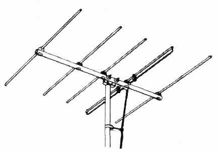
Yagi antenna — (YAH-gee an-TEN-uh) Pronunciation Key noun [RF Engineering] A Yagi antenna is a directional antenna consisting of multiple parallel elements in a line, usually half-wave dipoles made of metal rods. The functional elements of this directional antenna consist of a driven element (aka signal, one or more passive directors, and a reflector, arranged in a linear fashion along a boom. It is widely used in radio frequency (RF) communications for applications such as television reception, amateur radio, and wireless networking due to its high signal gain and focused signal directivity.

The Yagi antenna exists because of the need for enhanced signal directionality and gain in RF communications. By utilizing parasitic elements, the antenna improves reception and transmission efficiency, allowing signals to be sent and received over longer distances while minimizing interference from unwanted directions.

The primary effects of a Yagi antenna include improved strength in a specific direction, increased communication range, and reduced interference from signals coming from undesired directions. It is commonly employed in broadcasting, satellite tracking, and point-to-point communication systems.

A Yagi antenna's performance can be altered by adjusting the number, length, and spacing of its elements, which impact gain, bandwidth, and directivity. It can also be fine-tuned by modifying the placement of the reflector and directors to optimize performance for a specific frequency range.

The Yagi antenna was invented by Japanese engineers Shintaro Uda and Hidetsugu Yagi in the 1920s. It is often referred to as a "Yagi-Uda antenna," recognizing both contributors. The design became widely known after Yagi introduced it to the Western world, leading to its widespread adoption in radio and television technology.

Yagi_TV_antenna_1954 with 5 horizontal elements attached at right angles to a support boom. The assembly is mounted on a vertical pole and has a twin-leaded insulated coaxial wire leading downward
Wikipedia's Drawing of Yagi–Uda VHF television antenna from 1954, used for analog channels 2–4, 54–72 MHz (U.S. channels). It has five elements: three directors (to left) one reflector (to right) and a driven element which is a folded dipole (double rod) to match the 300 Ω twin lead feedline. The beam direction (direction of greatest sensitivity) is to the left. The antenna is made of aluminum tubing and the elements are roughly 6 feet across.
Y Terms Index

Arrow pointing up, clicking will move to top of page.