3D Modeling with Altium Designer Version 21, 20, 19, 18, 17 or earlier
The 3D capabilities of Altium Designer 20, 19, 18, 17 and earlier not only include export of 3D models of the entire board, but also design rule checking of placment using both horizontal and vertical clearance constraints. Altium Designer version 6.8 from 2007 was the first to offer 3D visualization and clearance checking of PCBs directly within the PCB editor
The illustrations on this page depict the use of STEP models. All of the images below were made by viewing an Altium Designer PCB file in 3D mode and taking a screen shot of that. Labels were sometimes added using an image editor.
- The first image depicts a PCB file which has had a STEP model of a metal case and STEP models of three other PCBs placed into it. The metal case was drawn in Solid Works by a mechanical engineer. Altium Designer was used to layout three PCBs and then model them in relation to the case. The PCB designer was thus able to make sure everything fit and also aid the mechanical engineer in positioning mounting holes in the case.
- Note that the PCB shown on the left and labeled "COTS Board" was not laid out by our designer: A simple 3D body was made by the designer and brought in to enforce vertical clearance constraints for the parts on the board underneath it.
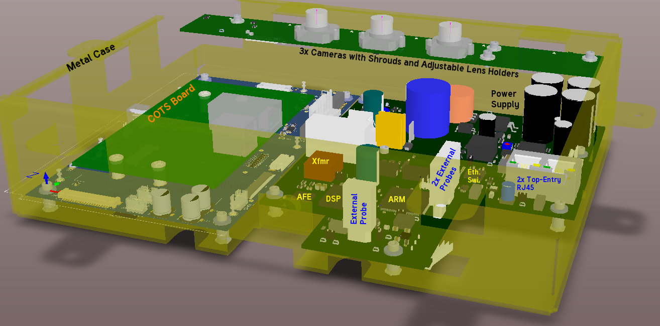
- Camera, Power Supply, ARM, AFE, DSP and Ethernet assembly - 3D design view - top.
- Below, the low-angle view of this assembly shows how Altium Designer can be used to explore the topology of a combined assembly. One could call this a "sanity check." The camera board resting above the other boards sets a limit on height of components below it. Screws that protrude from its backside as well as components loaded on its backside come into play as well.
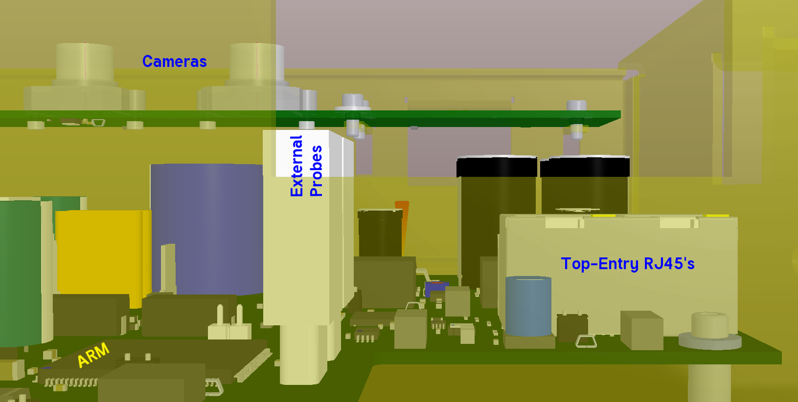
- Camera, Power Supply and ARM assembly - 3d-view - low-angle.
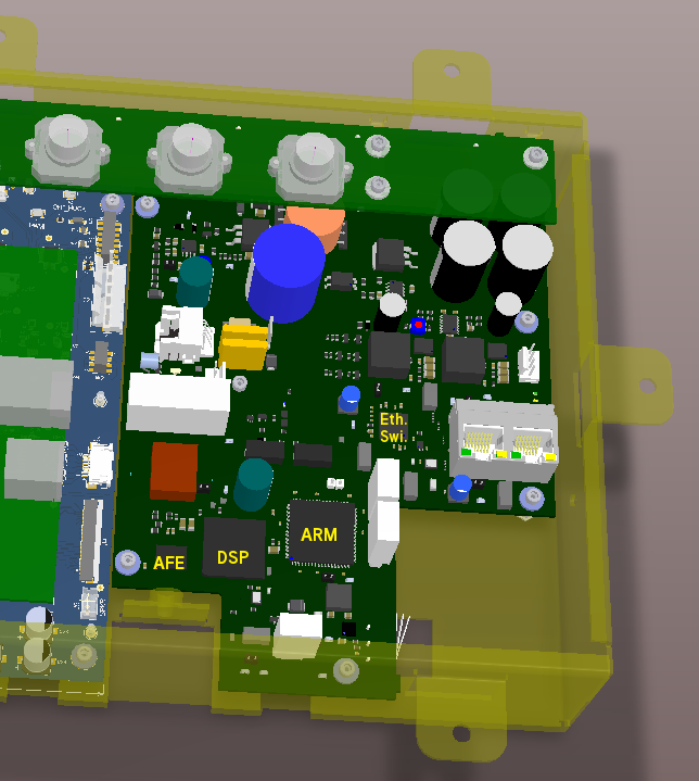
- Camera, Power Supply and ARM assembly - 3d-view - top view.
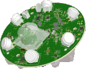
- One does not have to restrict oneself to the modeling of only physical objects. It was considered useful to add the camera focal axis to the footprint as a simple cylinder, especially since the focal axis of this particular on-chip camera is off-center. When the mechanical engineer imports the STEP model of the camera board into his CAD drawing, the exact focal axis location comes with it.
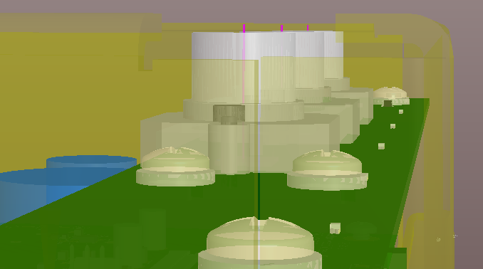
- Camera assembly: Camera focal axes modeled as magenta-colored cylinders.
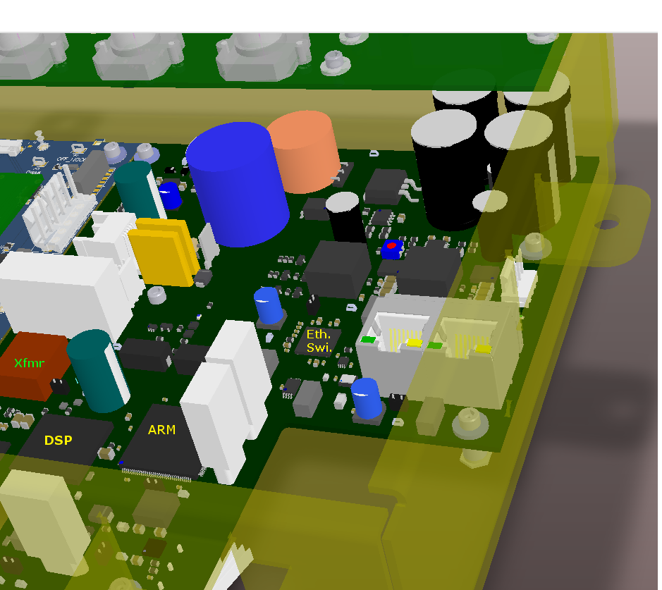
- Camera, Power Supply and ARM assembly - 3d-view - top view.
- Below is an example of Altium Designer's real-time DRC. A component was placed too close to a mounting screw and a "Collision" warning appeared in bright green. Note that this design was in an early stage and only a few of the footprints had been given 3D bodies. Altium Designer's component clearance checking works best when every single component footprint contains a 3D body.
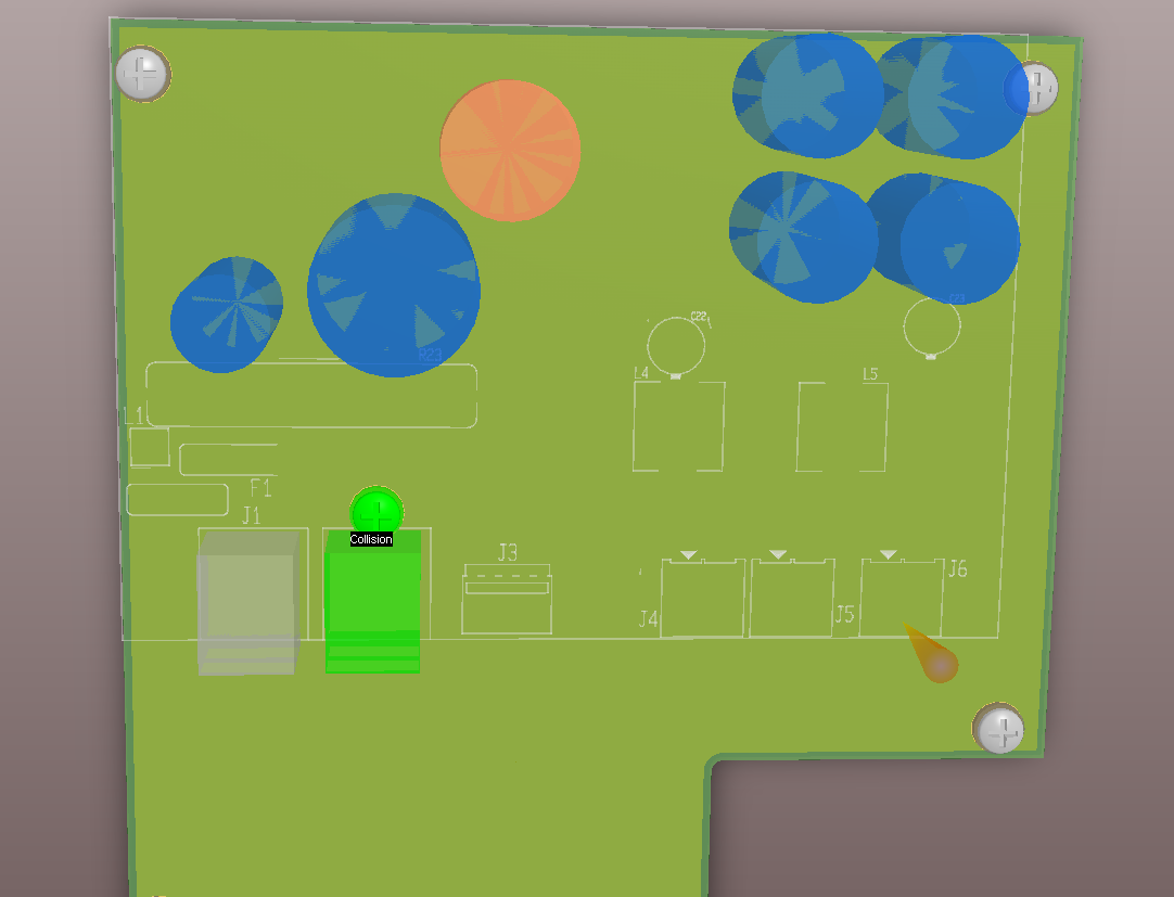
- Preliminary placement shows horizontal clearance violation
Golden Gate Graphics resides in Aurora, a suburb of Denver located in the middle of the
Rocky Mountain Front-Range High-Tech Corridor
, which includes the following
Colorado cities from south to north:
Fountain, Colorado Springs, Monument, Palmer Lake, Castle Rock, Highlands Ranch, Centennial, Englewood, Littleton, Denver, Golden, Aurora, Broomfield, Louisville, Lafayette, Boulder, Niwot, Longmont, Loveland, Ft. Collins and Greeley.


